

Case histories › Case history
Case history
Surveying industrial water with single beam echo sounders and USVs: mine water, frac pits and effluent ponds
How single beam echo sounders and unmanned survey boats are used for industrial water management: reservoir volume, sludge and sediment, and regulatory reporting. Worked examples cover mine tailings storage facilities, frac pits and effluent lagoon dredging.
At a glance
- Author
- Adrian McDonald, CEE HydroSystems USA, Inc.
- Application
- Industrial water management: reservoir volume, sludge and sediment, regulatory reporting
- Industries
- Mining, pulp and paper, oilfield services, industrial and municipal effluent treatment
- Examples
- Mine water management, frac pit monitoring, effluent pond dredging
- Equipment
- CEESCOPE™, CEE ECHO™, CEEPULSE™, CEE-USV™
- Software
- Hydromagic, HYPACK®
Introduction
Application of hydrographic survey methods and echo sounding technology to industrial water management has occurred only on a sporadic basis. In industries where water storage is an important part of the industrial process, for example metal and non-metal mining, pulp and paper processing, oilfield services, industrial and municipal effluent treatment, little in the way of defined standard procedures, common practices and favored equipment has evolved for bathymetry-related surveys.
Partly because of the poor usability of older sonar equipment and complexity of hydrographic software, site surveyors and engineers have largely not embraced sonar acquisition technology. Recent advancements in sonar equipment and the availability of simpler acquisition software, plus the development of unmanned survey drones to allow remote surveying from the safety of the shore has led to increased use of sonar methods for industrial water management. Some examples drawn from CEE HydroSystems’ customers are described in this article.
Industrial water challenges
Three common requirements call for surveying of industrial water reservoirs, as follows:
Requirement for water volume data
Water is a precious resource in industrial processes, and the available volume in impoundments is often an important but poorly understood variable. Techniques to estimate volume range from slope calculations, manual lead line or sounding pole measurements with a GPS, fish finder sonars, to hydrographic single beam echo sounders.
High quality hydrographic surveys present the advantage of being able to provide an accurate bathymetry map that may be used as the basis for a water height (stage) versus volume relationship that allows the understanding of water volume at various water levels.
Sludge and sediment management
Industrial reservoirs often fill up with solids, whether deliberately as in the case of an effluent settling basin or mine tailings impoundment, or as an incidental byproduct of the settlement of suspended particulates. As the “mudline” rises, available water storage capacity in the reservoir increases, and water residence time decreases for the same flow rate.
With inadequate residence time, effluent water quality compliance issues may arise and often periodic dredging is required to maintain plant compliance with discharge regulations. Effective bathymetric surveying helps plant engineers understand deposition regimes, determine a dredging schedule, and evaluate completed dredging for payment.
Environmental regulatory reporting
Artificial dams holding effluent water and solids from an industrial process are subject to regulation that may call for periodic reporting of the water volume or water extent.
Example 1 – Mine water management
Introduction
Water in the effluent stream of an industrial process is often at least partly recycled. Water costs may represent a significant operational expenditure, and water availability limitations – or volume excess – may be a risk in plant operations. For example, a mine tailings storage facility (TSF), which is the deposition basin for the rock fines also represents an emergency water supply for the mine. Knowledge of the available water volume is an important variable for site managers for emergency planning.
Too much water in a TSF, or water in the wrong place may elevate risk of dam failure. Mobile wet tailings spilling from TSF dam breaches has resulted in devastating environmental incidents such as occurred in the Bento Rodrigues (Brazil) and Mount Polley (Canada) disasters. By surveying the water impoundment, accurate bathymetry may be used to generate the available water volume. As regulations on dams call for more reporting on water volumes, mining firms have increasingly set up bathymetry programs using echo sounders.
In the mining environment, surveyors are not generating navigation charts but simply need to obtain measurements accurate enough for their needs. Understanding the accuracy requirement is a key point to minimize complexity in the overall acquisition process for operators for whom this is an uncommon task.
While a handful of point measurements using a sounding line and GPS is easy to grasp, it is inadequate to understand TSF volumes. A sensible single beam echo sounder (SBES) survey will provide volume at well over 90% accuracy, and with the right equipment is fast and easy. Advanced multibeam echo sounding, while allowing total coverage, does nothing to improve the useful accuracy of the volume estimate and does not have any useful application for TSF surveys. If using hydrographic software, survey lines may be repeated exactly, showing evolution of the TSF water pool.
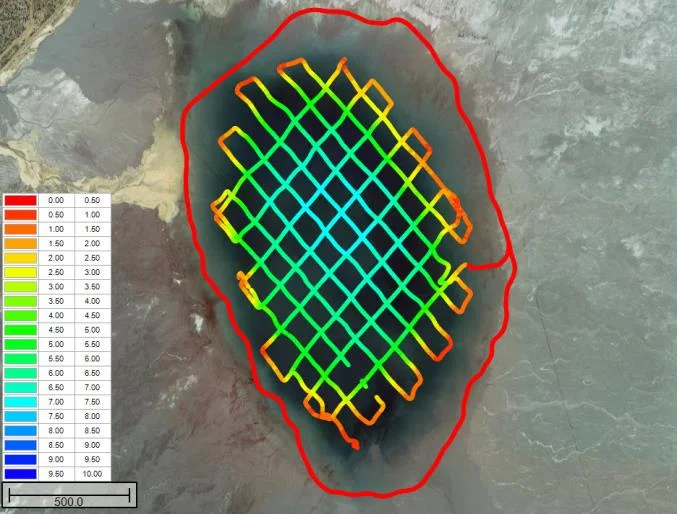
Drone survey boat (USV) applications
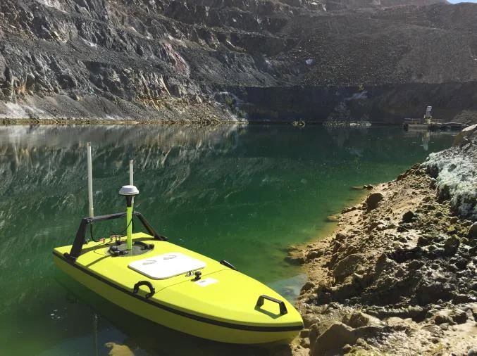
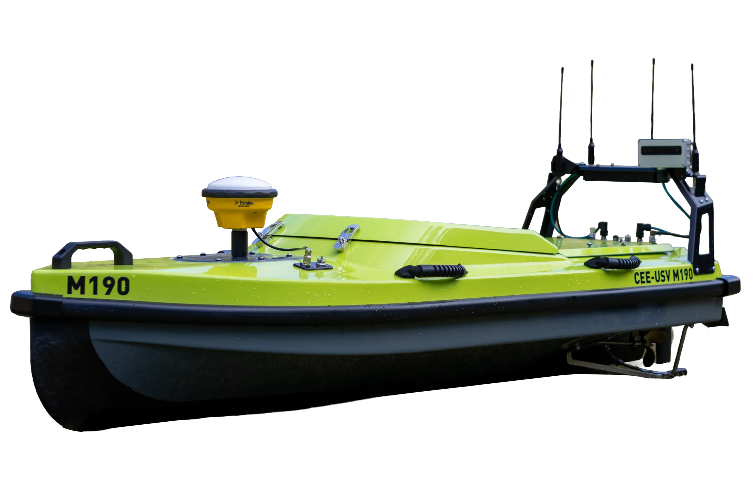
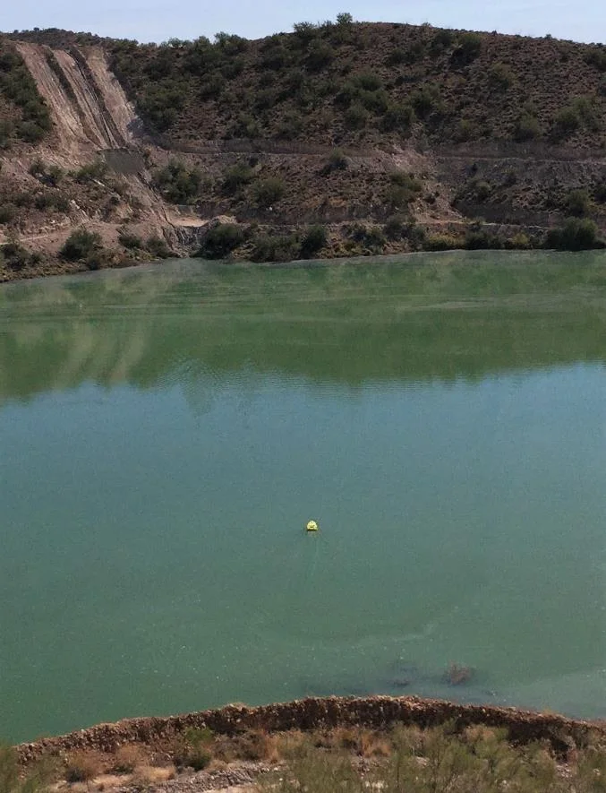
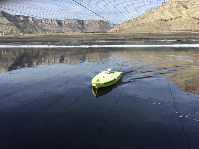
The TSF presents a good application for unmanned survey boats (USV) when the water is easily accessible and convenient shore control point(s) may be established. However, USVs are generally limited to small and medium sized impoundments; as the TSF area gets larger, unmanned surveying becomes increasingly impractical.
In addition to the convenience and time savings that may be realized by launching a small remotely-operated boat instead of mobilizing a manned boat, safety is improved with no personnel on the TSF and no requirement for personnel recovery / rescue contingencies.

RTK site networks
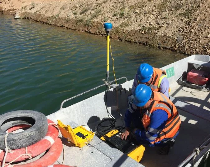
Mine sites always have RTK networks for surveying and heavy equipment location. Sometimes, these site RTK GNSS rovers are incorporated into the bathymetry program. This now calls for integration of discrete separate components – GNSS, echo sounder and software, increasing the system complexity.
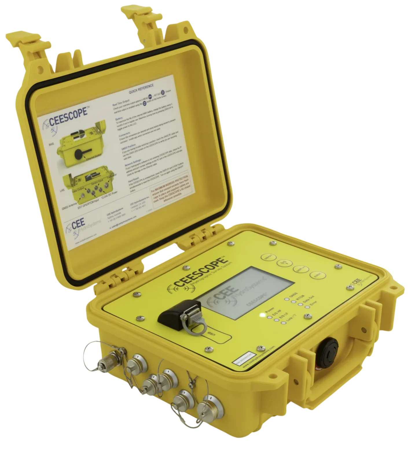
However, mine bathymetry programs are successful when complexity is minimized so site surveyors do not need to become hydrographic equipment setup experts. Avoiding the site RTK and instead using an “all in one” echo sounder and GNSS system such as the CEE HydroSystems CEESCOPE™ has been very effective where instituted. As the water level is not varying during the survey, and RTK-grade XY accuracy is not required for typical volume estimates, eliminating the site RTK network link is a positive step for usability. Water elevation is easy to obtain without bringing RTK complexity to the hydrographic program where it might not really be needed.
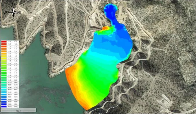
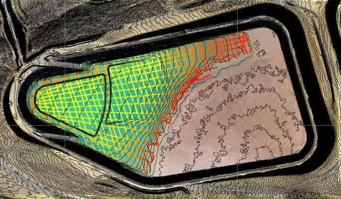
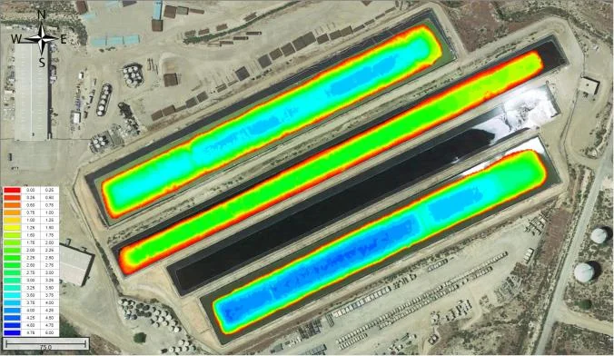
Tailings pond bathymetry, exported from the hydrographic software in XYZ “point cloud” format can be merged with aerial drone orthophotography to give complete site digital elevation models (DEM) as shown in Figure 5. In addition to understanding the amount of water in the TSF, the DEM shows total available capacity of the impoundment as the TSF is filled.
Understanding tailings deposition
Standard 200 kHz frequency SBES performs well for surveying the TSF mudline; the tailings / water interface is easy to detect. Therefore, dual frequency echo sounders are not necessary for TSF mudline surveys. However, the sub bottom water content of deposited tailings may be a useful measure to understand compaction and deposition regimes.
Water content at the mudline is very high and the solids content increases slowly and gradually through the sub bottom profile. Even low intensity echo sounder energy may penetrate substantially through the tailings deposit and the penetration will differ markedly depending on the level of compaction. Low frequency sonar (eg 24 kHz or 33 kHz) echo sounder may penetrate as far as 10 m through tailings and the comparison or relative penetration at a fixed sonar energy has been used to infer relative compaction in a TSF1. While results from a dual frequency echo sounder may offer some qualitative insight, no quantitative approach exists that allows echo sounder results to be related to physical properties of the deposited tailings.
Pit lakes and process water
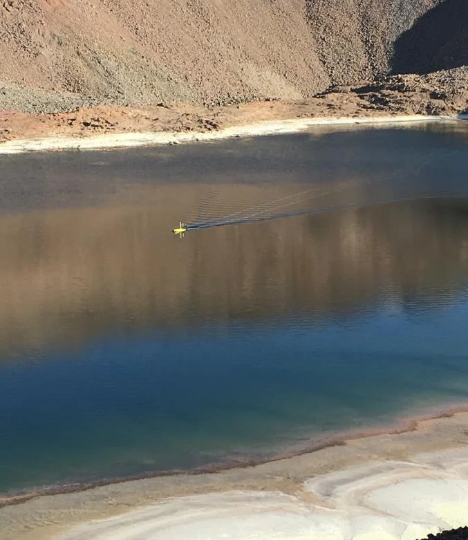
With access to a USV, mine engineers can use the survey capability for all site water reservoirs – not just the tailings impoundment. This includes even low pH leach solutions or pit lakes where access on a manned boat may be impossible, not merely inconvenient. With short exposure times to the mine solutions, even aggressive low pH solutions may be surveyed with a robustly designed USV using high grade corrosion-resistant materials.
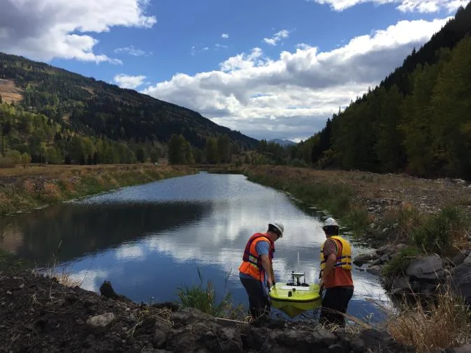
Process solutions may have abnormal sound velocity, and sonar attenuation may be very high owing to the high concentration of dissolved constituents. Dual frequency echo sounders (24–33 kHz) are needed to penetrate adequately for deep reservoirs. For leach solutions, 200 kHz sonar may penetrate no further than about 10 m (33 ft), compared to over 100 m in standard seawater.
Example 2 – Frac pit monitoring
Introduction
The process of hydraulic fracturing “fracking” for recovering shale gas involves creating artificial fractures in the rock to release gas to the well head. Large volumes of fracking fluid, primarily water, is injected into a well bore under high pressure to generate the fractures. While flowmeters may indicate usage for payment to the landowner supplying the water, the volume of excavated water storage “frac pits” or natural ponds is often unknown.
Towards real time monitoring
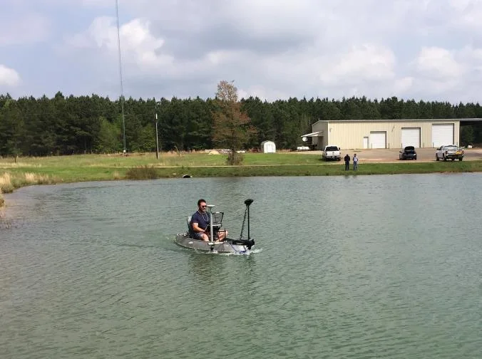
Oil field service companies have successfully instituted frac pit monitoring programs based around modern single beam echo sounding using small manned boats and USV drones. First, a small USV or for larger ponds, a one-person boat is deployed to generate a bathymetric map using a single beam echo sounder and GPS.
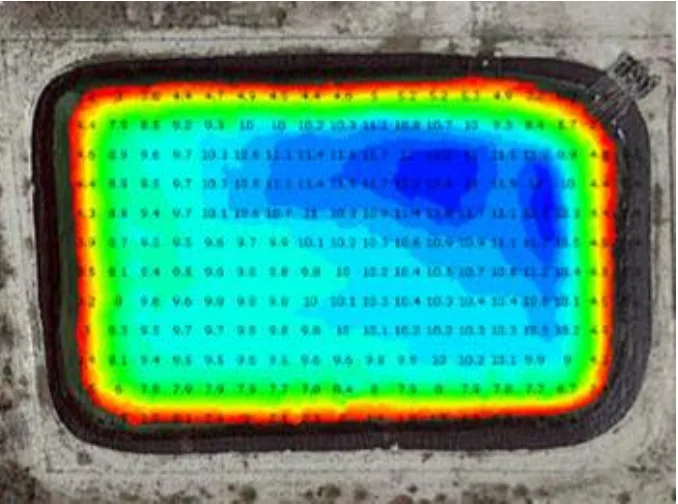
Once the bathymetry of each pit is established, a water level recorder may be installed at each site to provide a continuous level indication to the operator via satellite link. Using the strapping chart generated by Hydromagic or HYPACK software used for the bathymetric survey, operators can get a real-time view of their available water volume resource at multiple sites with no need to visit the site or re-survey. Drone boat technology is often key to the success of these programs, allowing field crews to visit multiple sites per day.
Echo sounding equipment upgrades
Early echo sounding equipment used on frac pit survey boats were simple “smart” transducers with basic signal processing. As the absolute accuracy requirement of the frac pit surveys is not particularly stringent, reducing capital investment by saving money on the sonar was attractive. However, over time it became clear this cost saving came at a price.
Often the excavated frac ponds are lined, with hard reflective surfaces. On occasion, the inexpensive echo sounders were unable to provide consistent results in the frac pits, with double reflections and inconsistent bottom tracking calling for a resurvey or substantial data editing.
As the value of the water management benefits of frac surveys were better realized, additional investment in better echo sounding (and GNSS) equipment was possible. Replacement of smart transducers with survey grade echo sounders such as CEE HydroSystems’ CEEPULSE™ or CEESCOPE™ eliminated onerous data editing tasks and with the large number of surveys being conducted, significant time could be wasted in editing data acquired at a low quality to start with.
Example 3 – Effluent pond dredging
Introduction
Industrial effluent treatment involves removing solid and dissolved contaminants before water may be discharged to the environment or sewer system. Effluent lagoons are used in municipal water treatment and industries such as paper production. The effluent water passes through several bays that are designed to allow solids to drop out, taking with them particulate contaminants.
As the lagoons fill with material, periodic dredging is needed. Aeration systems are usually installed to oxygenate the water to aid in digestion of organic solids in a continuous battle against the buildup of sludge.
Benefits of the sonar approach
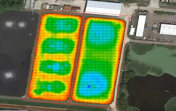
Effluent system operators or dredging subcontractors may benefit from the consistency and detail afforded by a compact hydrographic survey system. With a hydrographic sonar, identification of smaller scale deposition features is possible – such as the hole scoured out of the lagoon in Figure 10. The performance of changes to the aeration system or circulation pattern in the lagoon may also be evaluated.
The use of an echo sounder not only improves achievable survey detail but the duration of the survey and the time spent with people on the lagoon is drastically reduced. Manual sludge height measurement methods involve laborious point measurements with what is basically a long stick, or hollow tube – Sludge Judge® – to determine the sludge buildup in a grid pattern staked out along the lagoon. The manual methods suffer from operator dependence, as they are based to some extent on interpretation or “feel”. Using an echo sounder brings consistency to measurements with the interface depth characterized as the top of the sludge consistent within a survey and between surveys.
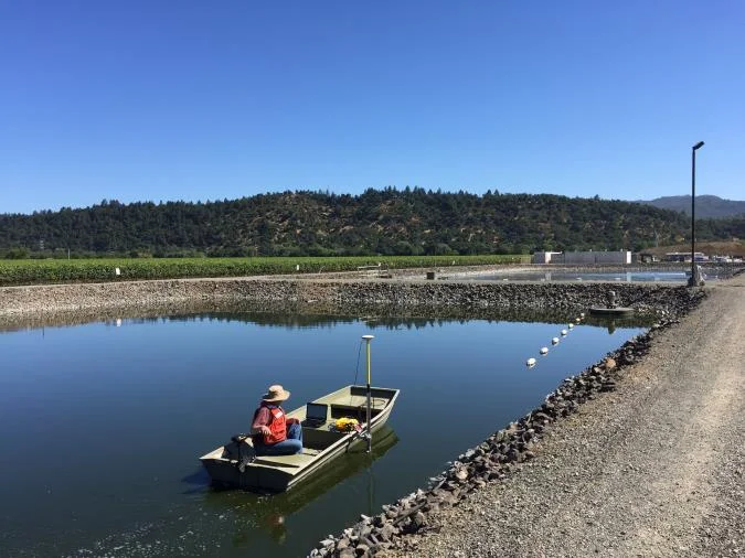
Often, access to the effluent pond is difficult for a manned boat. The sides may be steep, the pond may be small and / or shallow, and the material inside the pond may be hazardous. In this case, a USV becomes a good option for safe, fast surveys.
Where is the “hard bottom”?
Often, there is a desire to be able to realize the lower “hard bottom” surface using the echo sounding equipment in addition to the top of the sludge; the difference being the sludge volume. While manual methods using the Sludge Judge® allow the operator to hit the hard bottom by forcing the tube through the entire sludge layer, achieving a similar result with a sonar system is more difficult.
The thick sludge layer present in effluent lagoons – the lagoon may have been in operation for over a decade since dredging – means that bathymetric echo sounders typically do not have the output power to penetrate through the deposit. In addition, the relatively small water column presents problems with sonar reverberation, obscuring sub bottom details with spurious and unavoidable double, triple, and quadruple reflections from the sludge surface to the echo sounder transducer.
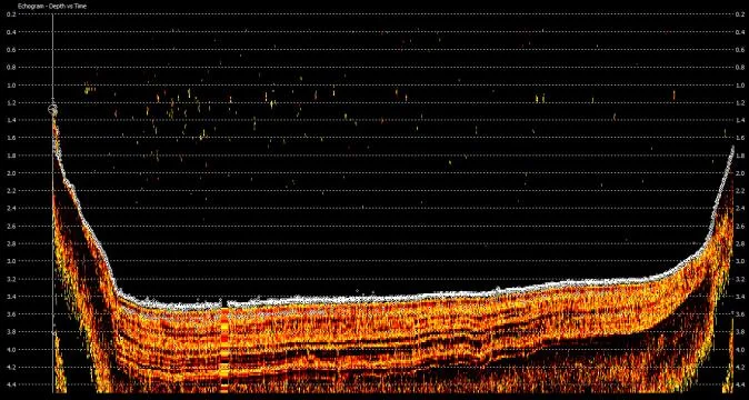
However, for recently deposited material, using a dual frequency 24 / 200 kHz or 33 / 200 kHz echo sounder may be able to provide a direct measurement of the sludge volume by using the high frequency return for the top of the sludge and the low frequency return for the pond bottom. The success of this characterization depends on the water column height (more water improves results) and the sonar penetration characteristics of the sludge – principally water content – in addition to the height of solids accumulated.
To evaluate the sludge deposit using sonar, hydrographic software such as HYPACK® or Hydromagic must be used with an advanced echo sounder like the CEE HydroSystems CEESCOPE™ or CEE ECHO™ that outputs not only the depth readings but also the full water column echo envelope trace.
While there can only be two digital depth readings per echo sounder ping, each ping presents substantially more information than merely the two depth results. The echogram shows the entire sonar intensity response from the surface to the maximum depth of penetration. Using hydrographic software, the surveyor can identify the appropriate bottom surface shown on the echogram visualization as the “hard bottom” and ensure the low frequency depth results recorded match the correct surface.
References
1: Johnson, A.N, Martin, P, Burkhalter, C, Krieger, G, Balge, Z, Lutes, K. New Remote Sensing Systems for Improved Planning and Management of Mine Tailings Storage Facilities. Proceedings Tailings and Mine Waste 2016, Keystone, CO, USA.
Planning a similar survey?
Tell us about your site and we’ll recommend the right equipment.
Talk to us →
More from the field
6 Jan 2026
Trimble RTX for accurate wastewater sludge comparison surveys with the CEE-USV™
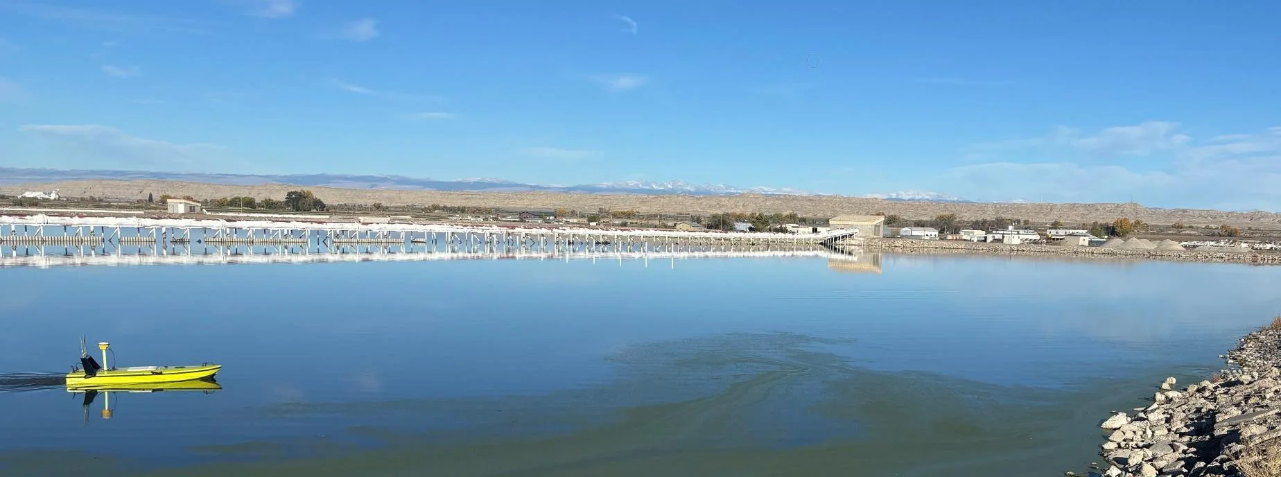
Team Lab monitors sludge in hundreds of wastewater lagoons with the CEE-USV™. Adding a CEESCOPE™ with Trimble CenterPoint® RTX in 2025 gave about 1 in (2.5 cm) vertical accuracy for the lagoon water level on every survey, so repeat surveys compare sludge volumes accurately without anyone going out on the water.
Team Lab monitors sludge in hundreds of wastewater lagoons with the CEE-USV™. Adding a CEESCOPE™ with Trimble CenterPoint® RTX in 2025 gave about 1 in (2.5 cm) vertical accuracy for the lagoon water level on every survey, so repeat surveys compare sludge volumes accurately without anyone going out on the water.
Read case history →
29 Apr 2022
CEE-USV™ surveys a wastewater lagoon in 45 mph winds and sub-zero temperatures
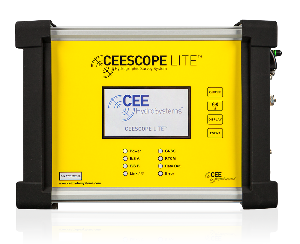
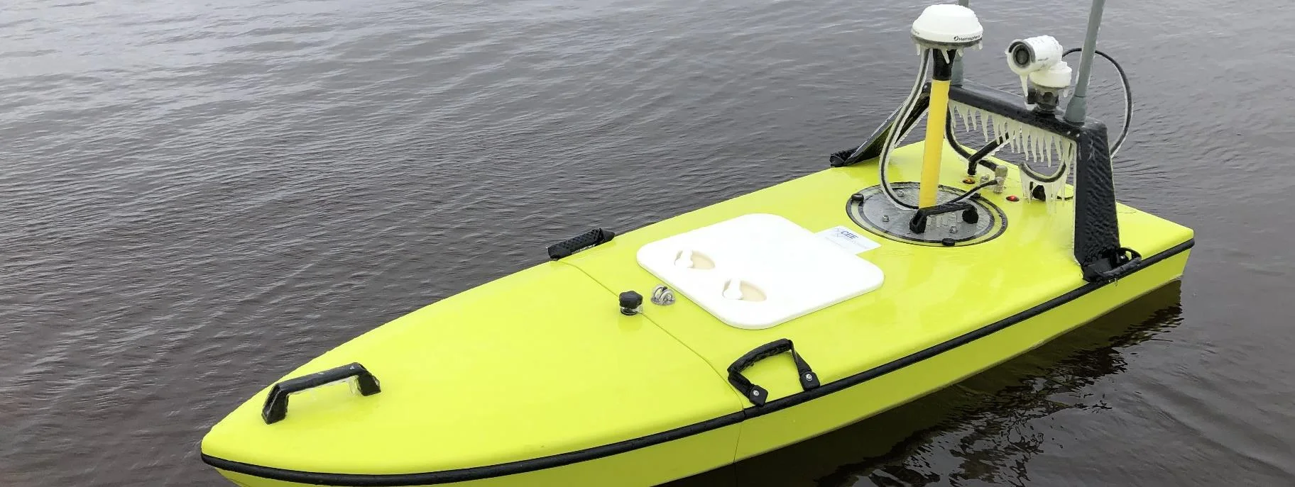
Midwest Planning LLC ran a CEE-USV™ survey of a Minnesota wastewater lagoon in late April, in 45 mph gusts and sub-zero temperatures, with the surveyor operating from a warm truck. Ice on the antennas caused some data drop-outs, but the on-board CEESCOPE LITE™ logged everything, so any gaps could be filled in Hydromagic.
Midwest Planning LLC ran a CEE-USV™ survey of a Minnesota wastewater lagoon in late April, in 45 mph gusts and sub-zero temperatures, with the surveyor operating from a warm truck. Ice on the antennas caused some data drop-outs, but the on-board CEESCOPE LITE™ logged everything, so any gaps could be filled in Hydromagic.
Read case history →
3 Nov 2021
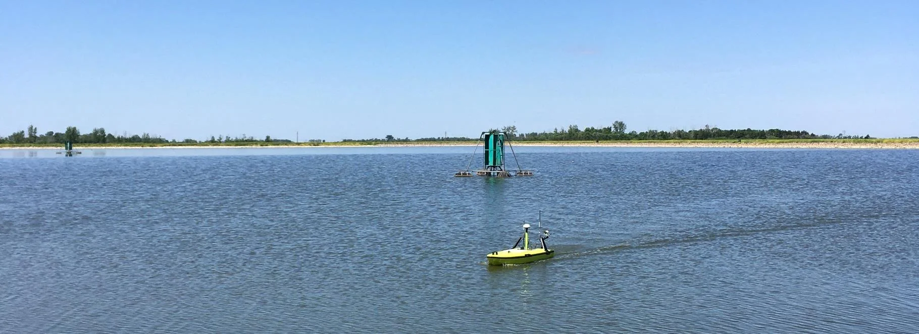
CEE-USV™ monitors sludge reduction in Minnesota effluent lagoons
TEAM LAB Chemical runs about 130 CEE-USV™ lagoon surveys a year in Minnesota and nearby states. Hydromagic 3D matrix grids give accurate accumulated and removed sludge volumes, compared year to year to evaluate treatments that can cut sludge volumes by up to 80%.
TEAM LAB Chemical runs about 130 CEE-USV™ lagoon surveys a year in Minnesota and nearby states. Hydromagic 3D matrix grids give accurate accumulated and removed sludge volumes, compared year to year to evaluate treatments that can cut sludge volumes by up to 80%.
Read case history →