

Knowledge base › Survey guide
Survey guide
How does a single beam hydrographic survey work?
The boat runs planned parallel lines, crossed by a few check lines, while the echo sounder measures depth and GNSS gives position. Get the basics right: a bar check to set the speed of sound, the right transducer frequency, sensible blanking, and RTK elevation if you need results as bottom elevations rather than depths.
200 kHz standard shallow water transducer
100–200 m max depth at 200 kHz
~9 °typical 200 kHz beam width
30 / 100 cm typical blanking, 200 / 33 kHz
For surveyors new to hydrographic equipment, here are the basic principles and the equipment characteristics that matter.
How is a survey laid out?
Hydrographic surveys are run as sections of parallel lines, usually planned in advance to make sure the area is covered. A smaller number of perpendicular check lines cross them, so the depths from each pass can be compared at every intersection.
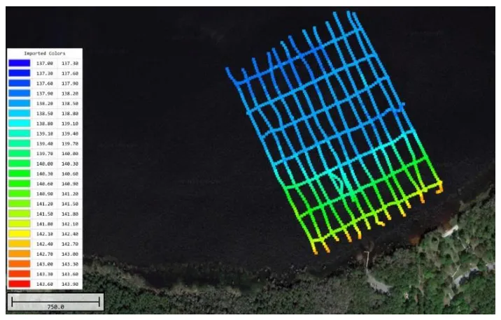
During turns, roll can affect the depths and the draft may change at low speed, so data is normally only logged “on line” when the boat is on a steady, straight course. Logging is paused while lining up for the next line.
Which transducer frequency should I use?
| 200 kHz (standard) | 24–33 kHz (low frequency) | |
|---|---|---|
| Best for | Shallow water surveys | Deeper water, or where suspended material or loose sludge is present |
| Depth resolution | Better | Lower |
| Maximum depth | Typically 100–200 m (328–656 ft) | Deeper |
| Penetration into sediment | Low: quickly absorbed, and suspended “fluff” can hide the true depth | Higher: can find a harder bottom under a less compacted layer |
| Transducer size and precision | Smaller, more precise | Larger, less precise |
200 kHz balances depth resolution (better at higher frequency), penetration through water (better at lower frequency) and transducer size (much larger at lower frequency). Higher frequencies are more affected by suspended sediment and have a shorter range.
What is a bar check?
A wrong speed of sound is a large source of error in single beam surveys. A bar check before the survey makes sure the correct sound velocity (SV) is used:
- Lower a flat plate under the transducer to several known depths.
- Compare the actual depth with the measured depth at each one.
- Adjust the echo sounder’s sound velocity until the measured depth matches.
At the end, the echo sounder is set to the average sound velocity over the water column. The error grows in proportion to depth, so shallow water surveys have a smaller possible absolute error. Temperature has the biggest influence on sound velocity; salinity is secondary.
When do I need a sound velocity profiler?
A bar check should always be done before a survey to check the instrument and set the average SV. A sound velocity profiler records SV continuously as it is lowered, giving a profile at points during the survey. The profile is loaded into the acquisition software to correct nearby data.
SV profiles are mandatory in lakes with seasonal thermoclines, or estuaries where the fresh water content changes a lot across the survey area.
Do I need to correct for pitch and roll?
In shallow water and inshore single beam surveys, boat motion (heave, pitch and roll) is usually minimised by choosing suitable survey conditions; a motion sensor is rarely used.
A general purpose 200 kHz transducer emits a cone of sound about 9° wide. The echo sounder records the first return from the bottom, so even if the boat tilts 5°, part of the beam still points straight down, and that nadir echo arrives first. This cancels minor pitch and roll.
A narrow-beam “engineering survey” transducer (around 1.5–3°) is more likely to measure a slant range when the boat moves a lot. Then you need to choose your survey conditions carefully, or correct with a pitch / roll sensor.
What is the blanking distance?
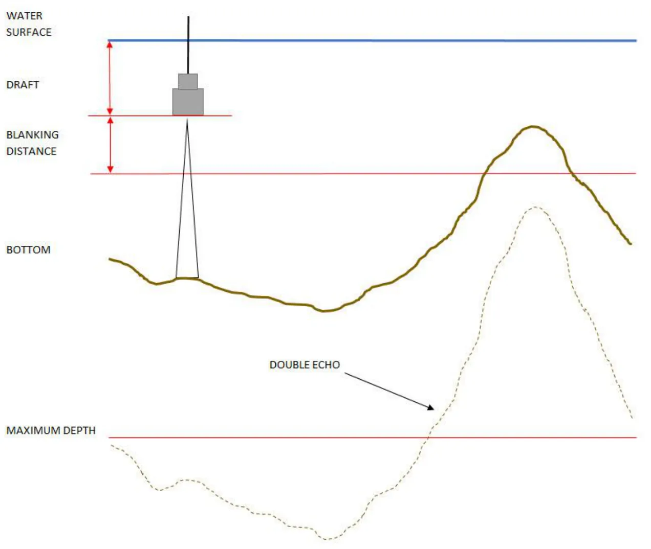
When the transducer pings, it “rings” briefly and can’t hear a meaningful echo until the ringing dies down. Multiplied by the speed of sound, that delay becomes a distance below the transducer: the blanking distance. Everything in that zone is ignored, which also removes air bubbles or debris just under the transducer. Typical settings are 30 cm for 200 kHz and 100 cm for 33 kHz.
What does auto mode do?
Survey echo sounders constantly adjust the ping as depth and conditions change; there’s no one setting for everything. Settings for 1 m of water would get no return in 50 m, and settings for a 100 m coastal survey would completely saturate the return in a 5 m pond. Auto mode finds the depth and keeps adapting the sonar to track the bottom, so the echo sounder works over a wide range of depths and bottom types without constant adjustment. CEE HydroSystems echo sounder algorithms are optimised for excellent bottom tracking in shallow water.
Manual settings: gain, pulse width and detection threshold
| Setting | What it does |
|---|---|
| Gain | Amplification applied to the received signal. Increase it to see weak echoes, for example when penetrating sediment. |
| Pulse width | Length of the ping. Longer pings penetrate further through water and sediment, but with less resolution. |
| Detection threshold | Changes which echo is recorded as the bottom. A low threshold records the very first returns; a higher threshold ignores the first part of the return and may follow a lower, deeper surface. |
How do I get bottom elevations instead of depths?
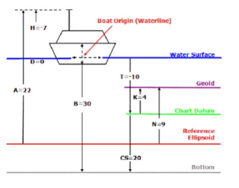
Use RTK GNSS elevation. The fixed antenna height above the water and the transducer draft below it are subtracted from the GNSS height, then the measured depth is subtracted to give the bottom elevation. The hydrographic acquisition software does this, giving results as absolute elevations above your chosen datum. See what is an RTK tide for the details.
Equipment used
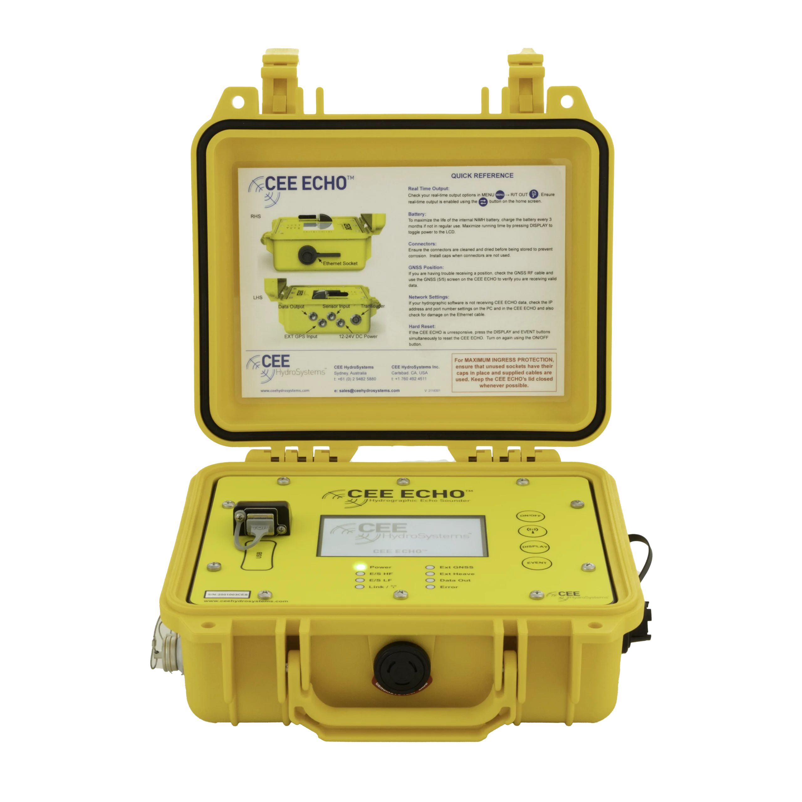
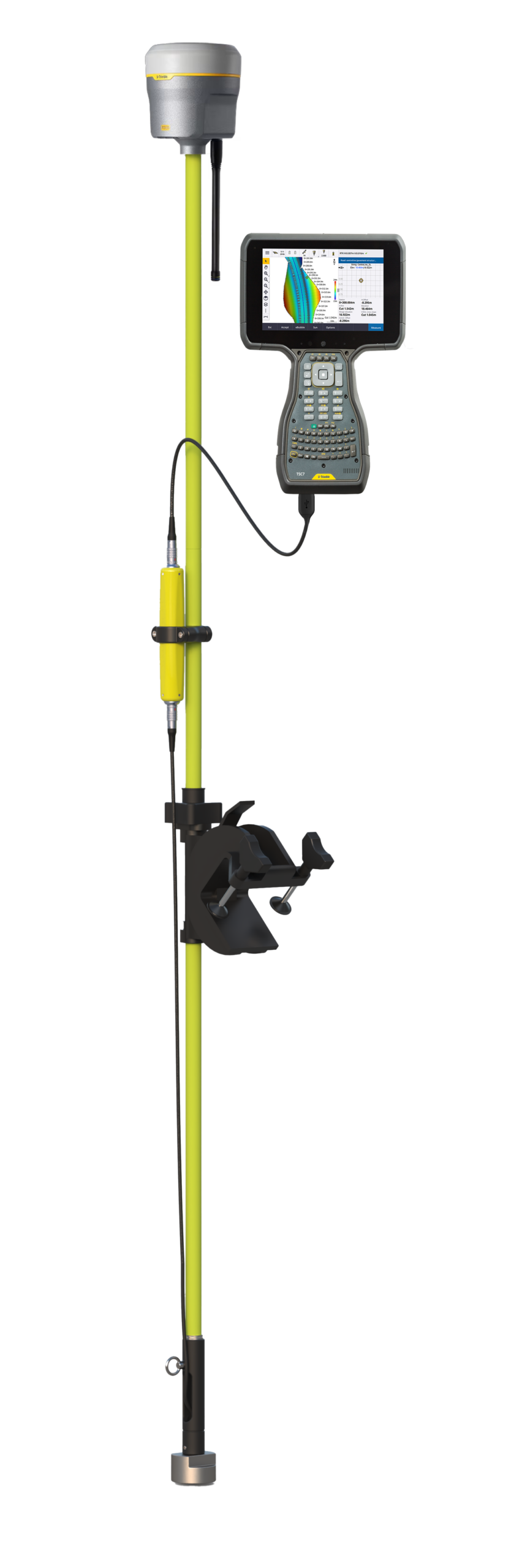
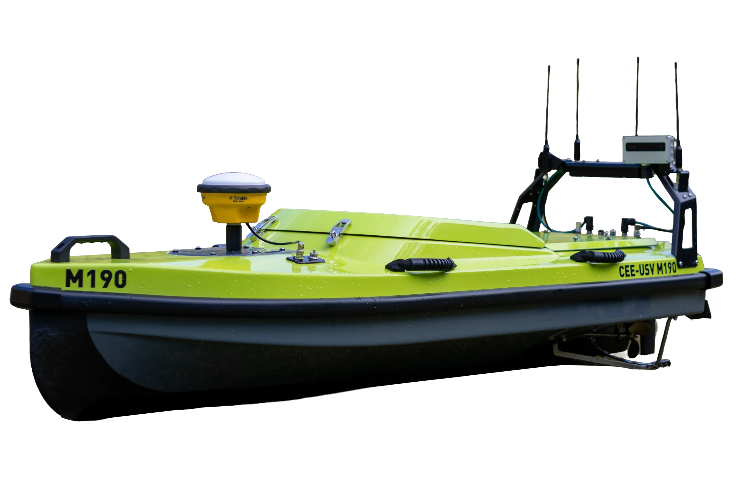
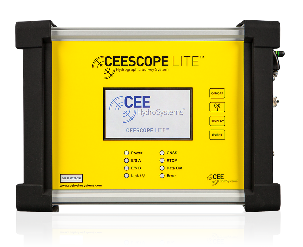
Single Beam Echo Sounder with Built-in GNSS
CEESCOPE LITE™
The whole CEESCOPE, in an even smaller footprint
View product
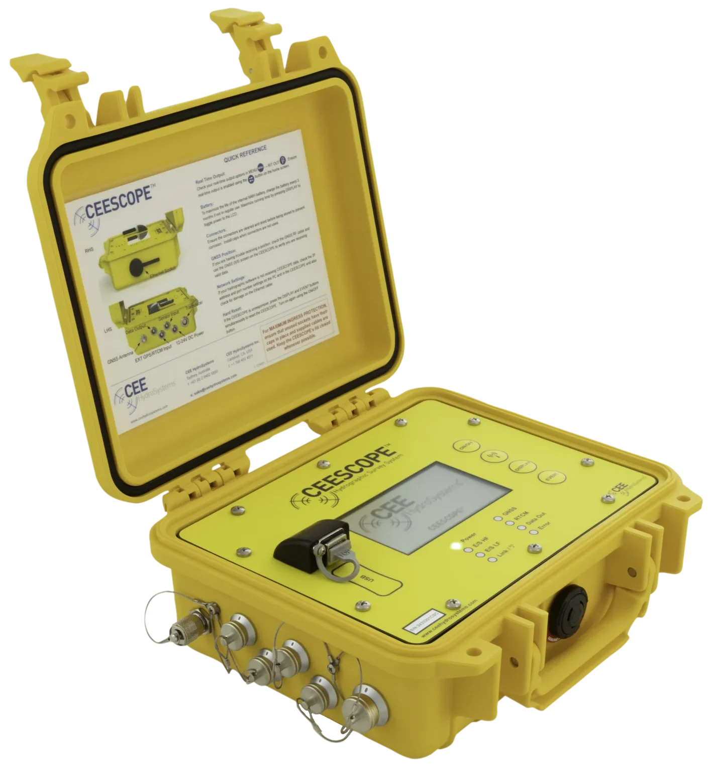
Talk to US
Need a hand with your set-up?
Our engineers answer survey questions every day.