On mine sites, pit lakes form as excavated mine pits fill with water; often the water is actually acidic, corrosive process leachate solution highly rich in dissolved components such as copper. The leachate may be removed and reprocessed to extract the desired metal. Usually, such pit lakes are too hazardous to survey on a manned boat so a USV is ideal. Existing land survey data may be used to determine the pit depth but over time sediment infill and pit wall collapse alters the volume of the pit. A pit lake in the Western USA was first surveyed using a standard 200 kHz setup on the CEE-USV™, without success. It was determined that a dual frequency 33 / 200 kHz echo sounder transducer would be required and this was supplied on loan from CEE HydroSystems. The 33 kHz low frequency channel was needed because of the extreme absorption of the sonar energy by the process solution in the lake; for example, a standard 200 kHz sonar transducer used for marine surveying to depths of over 350ft will only penetrate about 10-20ft through the pit water. At lower frequencies, absorption reduces significantly. The CEE-USV™ was operated in 33 kHz mode with the 200 kHz channel deactivated. Eye4Software Hydromagic was used to collect and acquire the survey data. Raw data were first edited to remove outliers and surface noise to generate a clean sounding file which represents the depth at each of the GPS position data points.
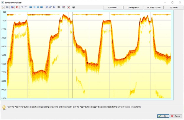
The profile views (depth along the boat track versus time) showed the bench structure and 33 kHz sonar returns were strong and clear. Areas where the pit had filled in were obvious at the North and South ends. The indistinct slopes shown on the depth profile echogram are a result of the unavoidable wide beam of the 33 kHz transducer. Typical pit slopes are near to vertical and the sonar beam simultaneously hits a very wide depth range, leading to a “fuzzy” echogram. The depth results along the slopes would tend to somewhat under-estimate the true depth.
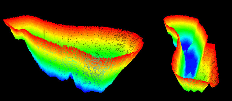
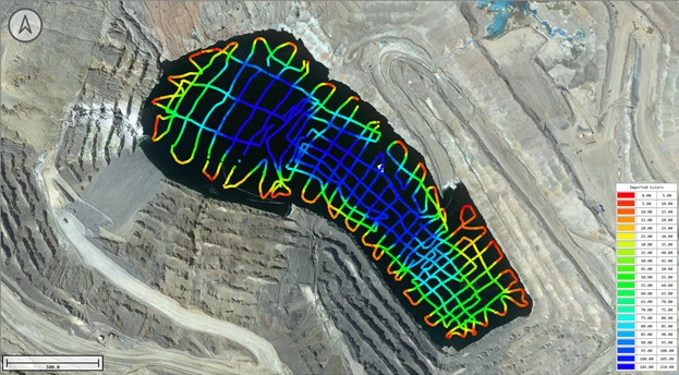
A TIN model surface was generated using the edited soundings to produce an equidistant 5 x 5ft spaced XYZ grid (Matrix) that was the basis for the pit water volume calculation. The grid points are plotted and colorized, and may also be shown as a 3D view. Before calculating the matrix, a shoreline (zero depth boundary) was drawn around the survey area, approximating the position of the waters’ edge. Owing to the shape of the pit, the survey was conducted from two shore control positions and one benefit of pit surveys is the availability of very highly elevated shore control positions, offering a great view of the USV for navigation around obstacles such as semi submerged pipes and cables.